 EnglishEnglish


Views: 0 Author: Site Editor Publish Time: 2026-07-15 Origin: Site


Upgrading or designing a modern cleanroom requires balancing strict ISO compliance against long-term energy demands. You must carefully evaluate the motor design powering your overhead filtration system. Your specific choice directly dictates operational stability and facility energy efficiency. Traditional legacy motors usually offer lower upfront costs but waste massive amounts of electricity. They also generate significant excess heat. This heat strains central HVAC cooling systems unnecessarily. Facility managers need reliable solutions to eliminate this waste. They must maintain precise environmental control concurrently.
This guide evaluates the engineering realities and system integration requirements of specifying an electronically commutated motor design. We will explore how modern units optimize airflow and simplify network control. You will learn actionable strategies to select the right equipment for your specific facility applications. You will discover practical implementation steps to modernize your sterile environments.
Efficiency vs. Heat: EC motors consume up to 50% less energy than AC counterparts, significantly reducing the secondary cooling load on the central HVAC system.
Dynamic Compensation: Built-in intelligence allows EC motors to automatically adjust fan speed as HEPA filtration media loads with particulates, ensuring consistent airflow without manual intervention.
Scalability: Networked EC FFUs enable zoned control and monitoring via centralized Building Management Systems (BMS), essential for large-scale ISO-certified environments.
Payback Reality: Despite a 20-30% higher initial CapEx, the typical ROI period for EC motor FFUs ranges from 12 to 24 months depending on local utility rates and facility size.
The traditional AC induction motor presents severe limitations for critical environments. These legacy systems waste considerable electrical energy during standard operation. They also produce excessive heat and offer poor speed control. Engineers struggle to maintain precise environmental conditions using outdated technology. Conversely, a brushless DC design defines the modern EC motor. It features built-in alternating-to-direct current conversion. Microprocessors inside these advanced motors provide precise operational control. They adjust rotational speeds digitally. This eliminates the mechanical inefficiencies inherent in older designs.
Secondary heat load reduction remains a critical design consideration. An electronically commutated motor operates at much higher efficiency levels than induction models. High efficiency directly translates to lower thermal emissions into the facility plenum. Less heat means your central cooling infrastructure works less intensely. You save massive amounts of electricity by reducing this secondary cooling burden. Facility chillers consume less power when plenum temperatures remain stable. This thermal stability protects sensitive manufacturing processes below.
Lifecycle longevity also sets these modern systems apart. They experience far less mechanical wear over time. Brushless designs eliminate physical brush friction entirely. They also feature soft-start capabilities programmed into the firmware. Soft starting prevents sudden power spikes during initial activation. It reduces physical stress on rotating fan components. These factors combined dramatically extend the operational lifespan of the equipment. You replace components less frequently. Your maintenance teams spend fewer hours on ladders performing reactive repairs.
Common Mistake: Facility managers often underestimate the sheer volume of heat generated by legacy alternating current fans. They compensate by over-sizing central chillers. This wastes massive capital.

How does the system handle static pressure fluctuations? Facility engineers must evaluate this metric carefully. Built-in intelligence allows the unit to monitor internal air resistance dynamically. The motor alters its speed automatically as the HEPA filtration media catches more particulates. This variable speed capability extends the lifecycle of critical filters. Air travels evenly through the pleats. This prevents premature filter face blinding.
Decision Lens: Always look for systems offering automated constant airflow (CFM) compensation. The system should maintain baseline CFM even when filter resistance increases substantially. This automation eliminates constant manual balancing interventions. It keeps the room fully certified between major maintenance cycles. It guarantees consistent laminar flow over your most critical process zones.
Noise creates severe operational problems in large-scale facilities. A single unit might seem quiet during isolated factory tests. However, high-density ceiling coverage compounds the noise significantly. You must account for this acoustic multiplier effect during the design phase. Workers suffer fatigue when ambient noise exceeds comfort thresholds.
Modern electronic commutation eliminates the disruptive hum often found in older frequency drives. The digital controllers operate smoothly across all RPM ranges. They utilize optimized fan geometries. These blade designs cut through the air silently. Specialized acoustic foam linings inside the housing further dampen vibration.
Evidence Marker: Specify acceptable Noise Criterion (NC) ranges for your project. ISO 4 spaces typically require ambient noise levels below 60 dBA. General pharmaceutical suites often mandate NC-45 to NC-50 targets. Always request acoustic spectrum data from your manufacturer.
Integration capabilities define modern ceiling grids. You must examine available communication protocols carefully. Modbus RTU, BACnet, and 0-10V analog signals dominate the current market. Robust communication allows centralized Building Management System (BMS) integration. Operators monitor thousands of units from a single dashboard. They adjust parameters globally in seconds.
Networked systems enable essential individual and group zoning. Facility managers can group multiple units into isolated control clusters. You can schedule night setbacks for a specific FFU zone during non-operational hours. This strategy saves substantial energy while keeping the room fully compliant. Sensors detect room occupancy and adjust the fan speeds accordingly. Digital controls provide real-time failure alerts. This immediate feedback prevents catastrophic contamination events.
Best Practice: Always map your digital zones to match your physical production zones. This alignment simplifies troubleshooting when localized contamination events occur.
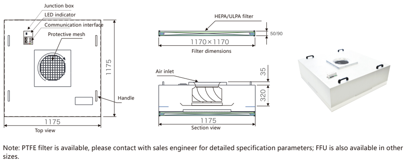
Physical dimensions dictate your installation success. You must address the weight of these specialized units early. The onboard electronics add slight mass compared to bare-bones legacy models. Ensure your specification matches the load-bearing limits of your cleanroom ceiling grid. Standard 2x4 T-grids handle lighter units easily. Heavy-duty walkable ceilings provide robust support for larger pharmaceutical models. Seismic bracing requirements also change based on total ceiling mass. You must consult local building codes before final procurement.
Top-load installations differ drastically from Room-Side Replaceable (RSR) designs. Top-load units require maintenance access from the plenum above. Technicians walk on the ceiling structure to swap filters. RSR designs allow technicians to swap filters from inside the room. They use specialized ladders and extraction tools.
Risk Mitigation: RSR units demand highly specific gel-seal or gasket configurations. You must ensure motor accessibility never compromises the primary seal during routine maintenance. A breached seal introduces raw plenum air into the sterile space. Polyurethane gel channels offer superior leak protection over traditional closed-cell neoprene gaskets.
| Installation Type | Maintenance Access Point | Ideal Application | Contamination Risk During Service |
|---|---|---|---|
| Top-Load | Above ceiling plenum | Microelectronics, Industrial | Moderate |
| Room-Side Replaceable (RSR) | Inside the clean space | Pharmaceutical, Life Sciences | Low |
Modern electronics simplify facility wiring significantly. These units offer streamlined electrical daisy-chaining capabilities. You can connect multiple motors along a single high-voltage power bus. This daisy-chain approach reduces overall wiring complexity drastically. It lowers installation labor costs compared to individually wired legacy units. You run fewer conduit lines across the plenum. Engineers must calculate voltage drops carefully across long daisy chains. Proper wire gauging prevents power starvation at the end of the line.
Common Mistake: Installers frequently ignore the voltage drop across long daisy-chained communication lines. Limit your network loops to manufacturer specifications.
Never compromise on documented testing. You must demand comprehensive factory acceptance testing (FAT) data. Vendors should provide individual unit leak testing results. They must also document airflow uniformity across the entire filter face. This proof guarantees your FFU fan filter unit for cleanroom ceiling meets strict ISO standards out of the box. Insist on seeing dispersed oil particulate (DOP) or polyalphaolefin (PAO) aerosol challenge test reports. These documents prove the filter integrity before shipment.
Assess the manufacturer's ability to customize form factors. Different industries require specialized construction materials. Microelectronics plants usually prefer lightweight aluminum construction. Pharmaceutical applications demand robust 304 or 316L stainless steel. Stainless steel resists harsh vaporized hydrogen peroxide decontamination cycles. You should also verify their ability to provide specific voltage configurations. Global facilities often require 277V or 230V single-phase options. Custom dimensions accommodate non-standard grid spacing in older retrofit projects.
Equipment delays derail facility schedules quickly. You must assess the manufacturer's supply chain stability. Ask about replacement part availability for your chosen fan filter unit. Local warehousing reduces downtime when unexpected failures occur. Evaluate the warranty terms closely. Industry standards typically offer one to three years of coverage for electronic motors.
Review these critical procurement steps:
Request comprehensive FAT documentation for every single unit.
Verify chemical and material compatibility for your specific industry.
Confirm local replacement part availability and warehouse locations.
Review the detailed electronic motor warranty terms.
Validate the software compatibility between the unit and your BMS.
Specifying modern filtration equipment drives facility success and long-term regulatory compliance.
Advanced commutation technology guarantees continuous operational stability under heavy loads.
Automated airflow adjustment reduces manual maintenance burdens significantly.
Networked digital controls streamline your environmental management processes.
Move from basic evaluation to precise specification immediately. Audit your current grid load capacities first. Consult a qualified HVAC engineer to map out your digital control zones. Finally, request detailed performance models from your shortlisted manufacturers. These models will help finalize your mechanical design correctly. Taking these actions protects your facility against costly contamination and energy waste.
A: Yes, but you must evaluate the existing electrical distribution first. Modern units might draw different peak currents during start-up sequences. You also need to ensure the current ceiling grid supports potential weight differences. Furthermore, you will need to install new digital control wiring or wireless communication modules.
A: These advanced units precisely control their RPMs to maintain constant airflow. They prevent harmful over-pressurization across the media face. They also prevent uneven particle loading inside the pleats. This precise control avoids the severe physical strain standard legacy motors place on delicate filter media.
A: Yes. They adapt perfectly across every classification level. In fact, they are practically mandatory for ISO 1 through ISO 4 classifications where ceiling coverage exceeds 50 percent. The massive heat and energy load from older technology would be completely unmanageable at that extreme operational scale.


