 EnglishEnglish


Views: 0 Author: Site Editor Publish Time: 2026-07-17 Origin: Site


Moving materials between varying ISO-class cleanrooms carries immense stakes. A single microscopic breach during ingress can compromise entire production batches. Cross-contamination poses severe risks to product integrity and patient safety. Because of this, facility engineers face intense pressure to eliminate vulnerabilities at perimeter boundaries. Passive transfer methods often fall short in modern high-tech manufacturing. Today, pharmaceutical facilities increasingly demand active air displacement over basic enclosures. Strict GMP and FDA regulations require these dynamic solutions to maintain rigidly controlled environments. Active systems actively sweep away ambient particulates before doors open. This guide serves as your technical evaluation tool. We explore core airflow mechanisms alongside crucial filtration specifications. You will learn how to specify the exact systems for your next facility upgrade. We carefully cover architectural integration risks. We also outline the validation documentation required for ultimate regulatory compliance. You can use this knowledge to ensure pristine manufacturing conditions.
Regulatory Alignment: A laminar flow pass box is essential for maintaining Class A/ISO 5 environments during material ingress/egress, directly supporting GMP Annex 1 compliance.
Interlock Reliability: Electronic cleanroom interlocks provide superior security over mechanical systems, preventing simultaneous door opening and ensuring necessary purge cycle times.
Validation is Non-Negotiable: Proper pharmaceutical equipment evaluation must include FAT/SAT (Factory/Site Acceptance Testing) documentation and integrated DOP/PAO testing ports.
Integration Impact: Wall thickness, HVAC load, and flush-mount designs dictate installation success and long-term cleanability.
Material transfer points act as the highest-risk zones for particulate and microbial ingress within any perimeter. People and materials constantly cross these critical thresholds. Without active air handling, hazardous particles migrate freely between adjoining spaces. When you transfer raw ingredients or finished vials, microscopic contaminants often hitch a ride. Traditional static enclosures do nothing to remove these surface particles. They merely prevent massive gusts of air from bridging two rooms. Modern facilities require a much more aggressive approach to contamination control.
Regulatory drivers continuously reshape how we handle these transfers. Evolving expectations in pharmaceutical manufacturing mandate stricter protocols. For example, EU GMP Annex 1 introduced rigorous guidelines regarding material transition. Regulators now expect active air displacement rather than passive transfer. Static pass-throughs no longer satisfy the requirements for moving items into Grade A or Grade B zones. Facilities must deploy dynamic systems to ensure continuous air flushing. sterile transfer procedures strictly prohibit relying on unventilated spaces.
A successful installation relies on clear success criteria. Zero cross-contamination remains the absolute goal for any design. Engineers must configure the unit to maintain specific differential pressure cascades. A proper setup provides verifiable audit trails for compliance audits. When an inspector reviews your process, they want data. They look for logs proving doors remained locked during the purging phase. Meeting these criteria ensures continuous regulatory alignment.
| System Type | Airflow Mechanism | Highest Compliant ISO Class | Contamination Risk Level |
|---|---|---|---|
| Static Enclosure | Passive (None) | ISO 7 / Grade C | High |
| Dynamic Enclosure | Active Vertical Flush | ISO 5 / Grade A | Near Zero |
Understanding internal airflow dynamics is crucial for proper specification. Recirculating vertical flow acts as an invisible shield against contaminants. Internal blowers push air through high-efficiency filters. The system directs this clean air downwards over the loaded materials. Target air velocities typically range from 0.36 to 0.54 meters per second. This specific velocity creates a highly uniform air wash. It actively sweeps particles away from the surface of transferred materials. Gravity helps pull these displaced contaminants down into lower return grilles. The system then routes the dirty air back into the blower plenum. Providing consistent laminar flow requires precise fan calibration.
The door locking mechanism plays an equally vital role. We must compare traditional mechanical locks against modern electronic options. Mechanical locks wear out gradually over hundreds of uses. Frustrated operators can occasionally force them open. Electronic or electromagnetic locks provide absolute security. They use powerful magnetic forces to keep doors firmly shut. This cleanroom interlock technology prevents simultaneous door opening under any circumstance.
Time-delay logic adds another critical layer of safety. We call this a programmable purge cycle. Doors cannot unlock immediately after someone closes the opposing side. High-efficiency filtration must first recover the internal chamber. The system must actively return the space to ISO 5 standards. This purging process typically takes a few seconds or minutes depending on chamber volume. Once the timer completes, the opposing door finally releases.
These units also manage complex differential pressure control. The internal chamber acts as a miniature active airlock. It maintains the intended pressure hierarchy between adjacent rooms. Positive pressure prevents dirty ambient air from entering cleaner zones. This aerodynamic balance ensures environmental stability.

Filtration standards define the absolute performance limit of the enclosure. You must specify HEPA or ULPA filters depending on your target classification. HEPA H14 filters capture 99.995% of particles sized at 0.3μm. ULPA filters capture even smaller microscopic anomalies. Integrating pre-filters is a mandatory engineering practice. Installers typically use G4 or F8 rated pre-filters near the return grilles. These initial filters trap larger dust particles and rogue fibers. They extend primary filter life significantly by preventing early saturation. This is a crucial consideration when specifying robust pharmaceutical equipment.
Material selection and fabrication techniques dictate long-term cleanability. Grade 304 or 316L stainless steel is essentially mandatory for these environments. Stainless steel resists harsh chemical cleaning agents perfectly. Continuous seam welding eliminates tiny cracks where microbes hide. Coved internal corners feature entirely rounded edges. These smooth corners prevent bio-burden accumulation. Wiping them down becomes incredibly simple. Operators can easily reach every single internal surface.
Proper instrumentation guarantees you can monitor performance actively. Integrated Magnehelic gauges display differential pressure visually on the exterior. They confirm proper fan operation and filter health continuously. Many designs include UV-C germicidal lamps for added surface disinfection. However, you must understand their specific limitations. Shadowing effects limit UV-C reach significantly. The light cannot penetrate the bottom of solid objects. Therefore, UV-C cannot ever replace manual chemical wiping. Finally, audible and visual alarms alert personnel about door status. A flashing red light warns operators when a purge cycle remains active.
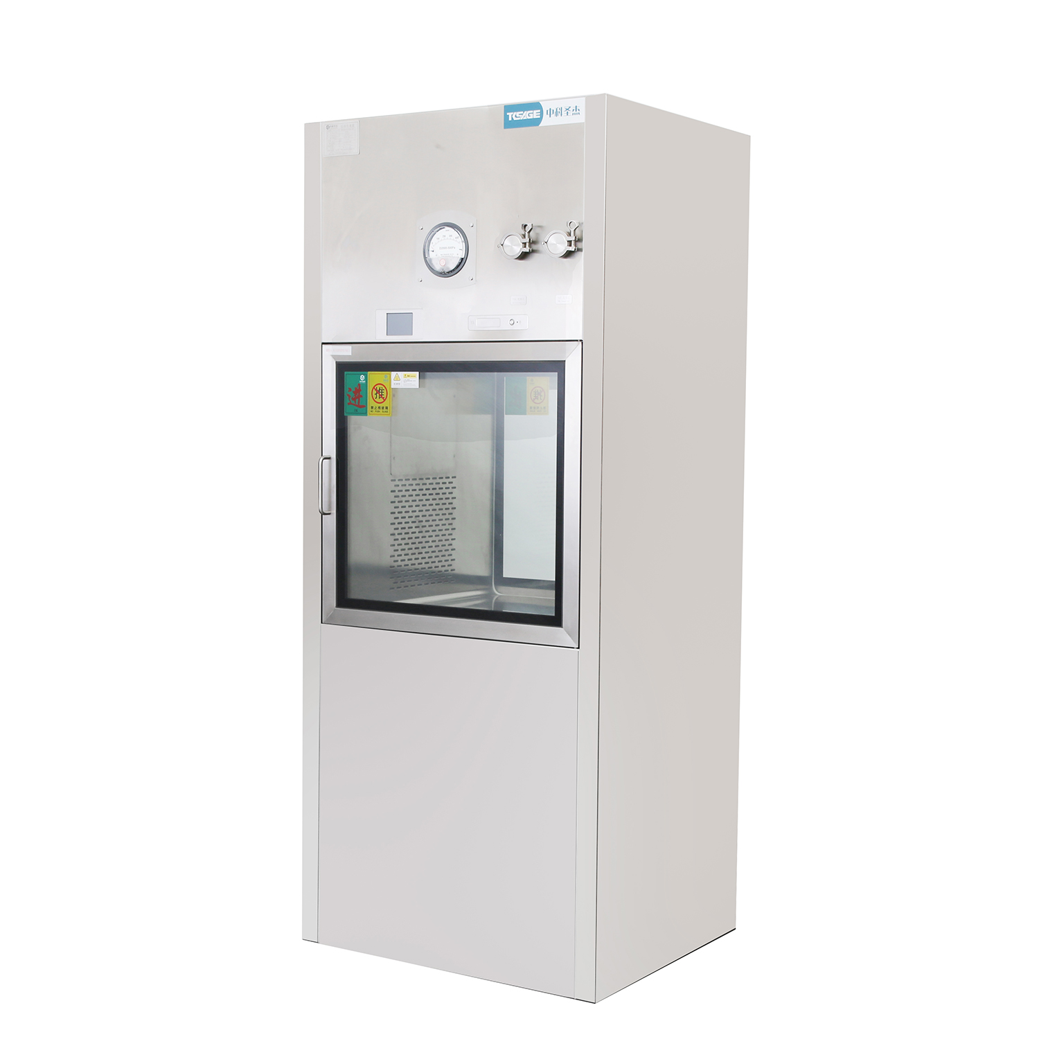
Installation poses several unique architectural challenges. Wall thickness varies greatly across different manufacturing facilities. Sandwich panel walls require completely different mounting flanges than stick-built walls. You must match the enclosure depth to your existing wall profiles precisely. Flush mounting prevents hazardous dust ledges from forming on the exterior. Protruding frames gather particulates and complicate routine room sanitization.
HVAC and power dependencies demand careful engineering review. You must decide whether the unit operates independently or integrates globally. Self-contained units use plug-and-play internal blowers. They operate entirely off their own power supply. Centralized HVAC connections require complex ductwork balancing. You must regulate external static pressure precisely. Internal blowers always generate localized heat. You must account for this newly introduced heat load. Small adjoining rooms can experience temperature spikes if left unmanaged.
Validation remains a rigorous hurdle during commissioning. Built-in testing ports are an absolute necessity for compliance. The design must feature DOP or PAO injection ports. Upstream sampling ports allow technicians to perform routine filter integrity testing. Technicians can execute these aerosol challenge tests seamlessly. They do not need to dismantle the stainless steel chamber. Specifying a fully testable pass box prevents severe compliance failures during annual inspections.
Selecting the ideal enclosure requires balancing standard offerings against custom engineering. Standard dimensions work perfectly for basic, manual transfers. Off-the-shelf units ship quickly and feature proven designs. However, complex workflows often require highly customized chambers. Automated VHP (Vaporized Hydrogen Peroxide) decontamination integration demands specialized sealing. Floor-mounted trolleys require designs lacking a bottom lip. Roll-in systems allow operators to push heavy carts directly through the boundary. Automated conveying systems need specialized motorized doors. You must map your operational workflow carefully before ordering.
You must evaluate potential vendors using strict regulatory criteria. Do not accept a unit lacking comprehensive documentation. A proper laminar flow pass box for sterile transfer requires extreme precision.
Documentation Verification: Demand evidence of comprehensive IQ/OQ/PQ documentation. Installation Qualification ensures proper physical placement. Operational Qualification proves internal systems function correctly. Performance Qualification validates the unit under real-world loads.
Airflow Validation: Request CFD (Computational Fluid Dynamics) mapping. This software simulation proves airflow uniformity in custom designs. It highlights potential dead zones where particles might linger.
Support Network: Evaluate local service availability. Clarify the warranty terms for critical components. Blower motors and logic boards require rapid replacement upon failure.
Use the following sequential workflow when evaluating custom configurations:
Determine the exact dimensions of the largest item crossing the boundary.
Calculate the required purge time based on chamber volume.
Select the appropriate stainless steel grade based on cleaning protocols.
Define the required alarm states for the control board.
Finalize the exact architectural trim kits needed for your wall type.
Choosing the correct enclosure requires navigating a complex decision matrix. You must meticulously balance physical footprint constraints alongside strict filtration efficacy. Interlock intelligence dictates your daily operational security. Robust compliance documentation guarantees smooth regulatory audits. An improperly specified unit jeopardizes the entire cleanroom perimeter.
We strongly encourage facility buyers to conduct a comprehensive site audit. Map out your exact material transfer workflows daily. Document the size, weight, and frequency of every item crossing the boundary. Consult directly with dedicated cleanroom engineering specialists. Draft a highly precise User Requirement Specification (URS) before soliciting vendor bids. Implementing these strict guidelines ensures unparalleled safety and seamless manufacturing operations.
A: A static box is a simple unventilated enclosure relying solely on passive transfer. It offers no active filtration. A dynamic version uses motorized blowers and HEPA filters. It actively washes materials using vertical air streams. Dynamic versions achieve ISO 5 compliance, making them mandatory for high-grade environments.
A: The exact duration depends entirely on internal chamber volume and fan speed. Typically, purge times range from 15 to 60 seconds. You must perform localized validation studies. The timer must run long enough for the HEPA filter to scrub the air back to baseline limits.
A: Retrofitting is generally highly impractical. Adding blowers, ducting, and logic boards requires significant physical space. Existing static frames lack the necessary plenum depth and structural support. Replacing the entire unit is substantially safer. Complete replacement ensures full compliance and proper factory validation.
A: Standard pharmaceutical guidance dictates rigorous testing schedules. You must perform DOP/PAO aerosol challenges at least annually. Many strict facilities opt for bi-annual testing every six months. You should also conduct routine particulate counts monthly to ensure continuous operational compliance.


